I’ve take a decision: force me to dedicate half an hour of my time everyday ( well, “more or less” everyday) to advance on my layout. That’s the only way to see something moving, given a sad event to my mother-in-law that make like impossible for me to have a whole afternoon during weekends.
This “little steps” approach demonstrates “very” effective ( you remember the Esopo story about the fox and the grapes? )
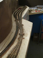
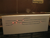
Anyway: I’ve finish to wire the DCC track power bus on the two intermediate peninsulas and done with one of the command panels at Burlingame!
The electronic driver board is one of the “old” Octopus from Tam Valley with fixed angle servo driver ( I’ve another two and want to check if I can use for turnouts or I’ve to relegate to drive in the future a semaphore blade or other animations). The main reason I doubt was my Fast Tracks point: it's very hard to hold in position.
Experimenting some different solutions for the music wire lever, I turned out with a solution as described in this past post: http://valleybeforesilicon.blogspot.com/2011/01/modified-actuator-for-servo.html
 Note a short piece of code 55 rail on top of the throw bar that hold the moving wire. I weld it and then made a slot with a Dremel abrasive saw.
This way I use the elastic wire play, to hold firmly the point rail against the side rail leaving the servos to reach his programmed angle. I’ve add to the octopus 8 relay to switch the frog polarity.
See this short movie of the result. To hide the actuator wire I plan to cover it with a replica of the pneumatic actuator that was used on the peninsula Coast line at the time ( and till now too! See this picture taken at 3rd ...OPS... 4th&Townsend in the City):
On the command panel, made by a Forex sheet, I’ve used DPDT switches (double pole) connecting one pole to the Octopus input and using the second to light a pair of Led indicating the valid route on the front fascia.
I use rectangular LEDs ( mainly ‘cause I’ve already have a bunch of it) but at the end the visual effect … was better than the “classic” ? To fit the leds just drill a couple of holes with your Dremel tool, then file with a little file (Oh, my poor English!) to obtain the squared corners.
Ok, here a short movie of the "thing":


2 comments:
Enzo,
I think the 'little steps' approach is a win/win solution. You get things done and other duties don't suffer too much. I'm trying to do it the same way (not really successfully, though).
Nice work on the layout, I'm in the 'track laying' phase as well and waiting for more servos and decoders from Duncan.
Keep the good work... 'one little step at a time'.
Ricky4208
Hi Ricky, you've a webcam pointed on mydesk? Also THIS post takes 3 steps:
yesterday I've prepared the text, todayI've loaded here... and tonight I've add the short movie! Takes so long but... it's moving.
Post a Comment