Here I want
describe one of the possible path to organize Operations on your layout.
This is the
way I found simple for me, but I understand it can not the same for everybody.
I’m not a Railroad “Pro”, more a modeler that like the Operations and this I’m
sure is reflected on my approach.
That said,
as a modeler… I start from the track plan!
1- Start to Plan your traffic:
Well, not
exactly, as my plan was designed with the fundamental railroad rule in mind:
rail traffic is generated from customers and rail service must have a revenue
to have a reason to be ( as any business adventure, I well know!)
So, after
reading a lot about SP Coast Division ( type of traffic, type of merchandize
delivered, history of some key-industries, history of some key-town along the
route, timeline for main freights types to identify what-was-when, etc….) I’ve
identified some subjects I like to model in the selected era and selected
locale:
- cement
traffic from manufacturer to distributor
- perishable
freight traffic with typical car management (cleaning, icing, loading, pre-cooling,
unloading )
- some
wood-chain industries ( not the lumber sawmills on the mountains that are
simulated from staging but furniture makers, building materials resellers , crates
manufacturers …)
- food
treatment chain ( canning , frosting, packing,
stocking, transfer to trucks for door delivery…)
- Chemical
raw materials supply for food treatments and gasoline for
automobiles, oil-derived products for industries and… to run trains motive power
- Express
mail traffic and LCL ( Less –than-Carload package shipping: what in modern time
is UPS-DHL and USPS delivery )
Setting
these “Given” in a list was a good
start, and I’ve used this “guideline” to find good names for all industries
along my track plan and “on the outside
world ( the two staging yards )” and design all service tracks ( spurs or
sidings) that will do the jobs.
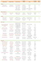
The result
was something like this document, that shows all main buildings along the path
from San Francisco to San Jose: my modeled section of the Coast Division.
 |
| Buildings list |
|
|
2- Shipper / Consignee and Lading list:
Well, after
this, and sourcing from the Customer list referred above, a second document
take shape.
This will
list all customers ( using Excel or any different spreadsheet software give you
the “sort” facility: sort by town, by lading, etc), setting also quantity of
cars they weekly need.
 |
| Shipper/ Consignee- Lading & Cars count |
If you’re interested
to download this document and use it as form to fill with your data, I’ve put
it in the Google document service as “public” ( no on line editing ) . here the
direct link:
Select “File”
menu and then “Download as..” and select the format you like ( Excel or Open
Office are obviously editable formats).
A good starting
source for Industries names, his location and lading type, can be the OpSIG (Operations
SIG of NMRA) database, that is available at their website, http://www.opsig.org, under “Online Resources,” and then
“Industry Database.”
This sheet will
be the basic document to plan your traffic, unrelated to which method you may select to implement ( Car-Cards
& Waybills. Switchlist, Timetable & TrainOrders, Warrants…. or any of
the “electronic” alternative , JMRI included)
3-
Timetable
Before
speak about this we’ve to prepare another “basic” : a Timetable of the “scheduled”
trains, passengers trains included if you plan to have it. To do this job, I
take as a good start a real Employee Timetable of a relevant year I want model.
For an example of some “vintage” SP Timetables, you can source on my page here:
http://enzofortuna.altervista.org/SP_doc.htm
Here is a
sample ( in progress as you see) of my ETT prepared for my layout:
Again this
is available to download at Google Docs using the same procedure as above:
You see
that I’ve listed regular and “named” trains, both passengers and freights. In
addition to these some 3rd Class “Extras” are generated (randomly or
when the OP session need some “excitement”).
Given the
number of operators my layout will have “normally” , I image to split the daily
time in 4 consecutive OP sessions. Anyway we will define this when the time of
a first “Round Robin” become a reality!
An important "visual" addition using Excel or similar software is the ability to generate a "Traffic diagram". This helps a lot to check train meetings and timings on the line.
Here is a good sample and explanation: http://mdodd.com/virginian/string_diag.html
4- “on hand” documents for your crew
All these
activities give you an organized basis to step forward with next action:
prepare documents to have “your Railroad running” in a prototyped simulation.
The
traditional choices, as said, are:
Any of
these methods have sustainer or detractors, but I want to describe in a next
post an alternative I want to follow ( at least as my first option ) given my inexperience
in car traffic planning: I want try to use the Operation section of JMRI , a
freeware software that maybe some of you know ( and use?) to program you DCC
decoders or display CTC panels.
So, wait ‘till
I find some time to drop another update here!


 -
- 


 -
- 